Application
Joint to compensate changes in pipe length,
caused by temperature changes in pipe
systems. For use with non-aggressive fluids,
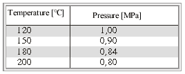
water, vapors and gases, for service pressures
and temperatures:
Technical description
A moveable part is inserted into the cast iron
body. Gland packing provides the seal.
Guiding rings ensure movement along the
axis of the pipeline.
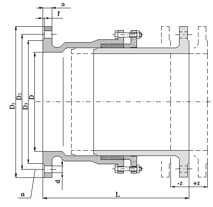
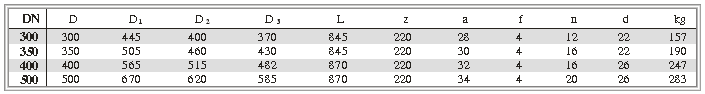
Connecting and face-to-face dimensions
Face-to-face dimensions are given in the table
below.
Flange connection dimensions as per
DIN 2501.
Flange faces as per DIN 2526, Form C.
Material
Body, moveable part grey cast iron
Packing bonnet grey cast iron
Guiding rings non-ferrous metal
Gland packing asbestos-free fibre
Testing
The gland expansion joint is tested as per
DIN 3230-3, ČSN 13 3060, part 2.
Installation
The expansion joint can be installed in
horizontal or vertical pipe-line. When
installed vertically the moveable part should
be uppermost. During installation it is
essential to set the face-to-face dimensions
correctly to make sure that the possible
expansion (contraction) of the pipeline is
within the allowable contraction (expansion)
limits of the expansion joint.
|